The Bayliner 175 restoration continues as we hammer out the final mechanical gremlins. After our recent lake test, we identified two critical “blind spots” in our engine monitoring: a leaking oil pressure unit and a complete lack of a fuel filter.
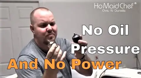
Here is the technical breakdown of how we plumbed a new oil sending unit using a specialized extension and added a clear-view fuel filtration system.
The Investigation: Solving the “Leaky Sender” Problem
During our engine priming phase, we noticed a slow leak from the original oil pressure sending unit. While the electrical part worked intermittently, a leak in the lubrication system is a non-negotiable failure point.
- The Fitment Challenge: On the Mercruiser 3.0L, the mounting point for the sender is in a tight recess. You cannot simply thread the bulbous sending unit directly into the block because it hits the engine casting or surrounding wiring.
- The Solution: We used a Jegs extension pipe (NPT thread). This moves the sender roughly two inches away from the block, providing the clearance needed for a wrench and preventing interference with the wiring harness.
- The Protocol: We cleaned the threads thoroughly before installation. Even though the unit looked “expired” (rusty), we used a crescent wrench and a half-inch ratchet to ensure a liquid-tight seal.
The Project: Monitoring and Filtration
Because our boat currently has an inoperative fuel gauge, we are “flying blind” regarding our range. To mitigate this and protect the carburetor from debris, we made two key additions:
- The Inline Fuel Filter: We found that this boat had no inline filtration between the pump and the carb. We installed a clear-view filter right before the intake.
- Technical Advantage: The clear housing allows us to visually inspect the fuel quality and verify if the fuel pump is actually delivering gas. If the filter is empty, we know we’re about to be using those paddles.
- PCV “Redneck” Engineering: We didn’t have the correct molded rubber hose for the PCV (Positive Crankcase Ventilation) valve to the intake breather. We crafted a temporary solution using standard rubber hose to ensure the crankcase is venting properly and not building internal pressure.
The Results: 25 PSI and 500 RPM
With the new sender wired up, we did a “dry run” (without water) for just a few seconds to verify the gauge.
- Oil Pressure: The gauge registered roughly 25 PSI at idle. While we saw 40 PSI with our mechanical test kit earlier, the lower reading is likely due to the electrical gauge calibration or the low idle speed.
- Idle Speed: The engine is currently sitting at 500 RPM, which is a bit low for this 3.0L. We’ll be bumping that up to around 650-700 RPM once we have it back on the water with the cooling system engaged.
Final Thoughts
The Florida weather is finally cooling off into the high 70s, which means we’re in a race to finish these projects before the “chilly” season truly hits.
Watch the full installation walkthrough here: Install Oil Sending Unit and Fuel Filter
While I’m finishing the mechanicals, Danielle is mixing up “Sunset Lemonades” (lemon juice, water, and a splash of liquor—no sugar) and preping new recipes. Our official shop is also live, featuring the gear you’ve seen in our videos. Keep an eye out for our limited-edition holiday gear dropping soon!
For restaurant reviews and weekly recipes, head over to www.dininginwithdanielle.com.
Oil Sending Unit For This Boat:
https://amzn.to/3265n4K
Fuel Filter:
https://amzn.to/2BVH9zF
Oil Pressure Tester:
https://amzn.to/325ZkNw
Alternator:
https://amzn.to/335JmEq
1/8 Sending Unit Extention Sourced From Jegs